
As you can see, the simulation of the air flow by a scoop (funnel) is a very complicated work but, the results and conclusions are very close to those I will show you next.
Let’s look at the scoop section below - without rotor. Because of the conservation of mass (we assume that the air density remains constant) and energy, the maximum volume of the air which flow (unconstrained) through this scoop/shroud is equivalent with the volume of a cilinder with radius (slightly) bigger then the minimum radius of the scoop. Usually, depending on the shape profile, this ratio (r2 / r1) varies between 1.2 to 1.6. So, using a scoop, in ideal conditions, we obtain an increase of a wind speed in the narrow section by square of this ratio.

To pass more air it's necessary an infusion of additional energy that ideally beeing extracted from the air outside. One solution to do this is adding a flange as an obstacle for the surrounding air which determines a little increase of the inlet flow.
When the volume (thickness) of the scoop (shroud) is significantly, then, the volume of the air displaced by this, bypass the scoop both inside and outside, in comparative equal parts.
Adding the rotor, in the best (ideal) hypothetical case (read about Betz’ law at: http://en.wikipedia.org/wiki/Betz's_law ) only 2/3 of this volume pass by the scoop and the speed decrease by three times. Practically, these numbers are smaller, the efficiency can be 75-80% of the maximum calculated.
Why using a scoop? In fact the wind cannot be concentrated, it only can be constrained to pass through a small area in order to increase its speed, that is to say, modifying its shape. This way, the rotator (or helix, blade, airscrew) diameter is smaller, quiet and it starts rotating at lower wind speed. Also, it may be possible to couple the generator direct with the rotor (without gear box).
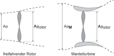
Actually, there are very few implementations of this type of turbines because their gain in efficiency is reduced and do not justify the extra cost of the shroud (scoop, case). In the upper picture, the equivalent diameter of the scoop is 1.5-1.6 times the rotor diameter, so, the maximum (theoretically) increase in speed can be approximately 2.5 times. Not so much as we expected!

For example, the WINDTAMER turbine presented in a videoclip on the first page isn't as efficient as the narrator say, the equivalent volume of the scoop is a cilinder with the diameter bigger by only 1.2-1.3 times the rotor diameter. And the assertion that it exceed the Betz limit is totally wrong, him probably didn't understand this law.
Read also: http://www.heiner-doerner-windenergie.de/diffuser.html
I made a couple of simulations on https://platform.simscale.com/ site to see how much can a funnel (or scoop) to increase the wind speed by constrain it to pass through a small area. Below are some examples:


As we can see, when using a nozzle the speed on outlet is a little bigger then the wind speed but not much more. Optimizing profiles (aerodynamic) or using flanges and other tips, this ratio increase more but also increase costs (using a long funnel).

Finnaly, depending by the shape of the shroud, a bigger or smaller fraction of upstream flow bypass the "concentrator" and other part of the flow energy is lost due to separations that appear when the flow change abrupt its shape or sectional area. I remarked yet that changing gradually only the direction (not the surface), the energy preserve:


This observation conducted me to the idea that a funnel can be used rather to bring the wind energy at ground level (or sea level), so the entire construction can be easier to accomplish (mounting the blade, the generator and so on at low level altitude).


However it remains a problem: such a funnel cannot easy follow the wind direction.
Recently, I hit on an idea of capturing more efficient the wind energy using an active nozzle and a positive feedback loop (like in tornadoes for example).
For now, I prefer do not make public the details. If you are an investor and you have a good design team and all you need is an innovator idea, please contact me at mircea.iancu.2011@gmail.com .

Ducted or shrouded wind turbines have been invented and reinvented throughout the 20th century. One such inventor was Dew Oliver, who installed his "blunderbuss," or ducted turbine, in California's San Gorgonio Pass in the 1920s. Historian Robert Righter notes that though Oliver claimed the turbine worked, that didn't prevent Oliver from being eventually convicted of fraud. (There should be a lesson in that.)
While many inventors opt for squirrel-cage rotors as a sure-fire means for extracting more energy from the wind than conventional wind turbines, others, such as Dew Oliver, opt for wind turbines encased in shrouds or ducts. As with squirrel-cage rotors and their curved deflectors, shrouded turbines are easy to visualize. Much like giant funnels, the shrouds concentrate or augment the flow across the wind turbine's rotor.
However, ducted turbines are often wrapped in mysterious, technical babble, such as diffuser augmentation, that is beyond the ken of most observers. Even supposedly sophisticated engineers have been snared by what at first appears to be a startling new technology "overlooked" for decades by everyone else.
Do augmented turbines work? Yes, of course. Cup anemometers work too, but we don't use them to produce electricity. Why? Because cup anemometers can't compete with modern, high-speed turbines. The same is true with ducted turbines. They have been tried--time and again--and found wanting.
Diffuser-augmented turbines can achieve conversion efficiencies much higher than conventional wind turbines with rotors of the same diameter. Consequently, ducted turbines periodically reappear in both the trade and professional press as a "promising" new technology--often in conjunction with a jump in the price of oil.
What is missed, however, is that a ducted turbine uses, well, a duct, and it is this big duct, or shroud, that increases the area intercepted by the ducted wind turbine relative to that of a conventional wind turbine of the same rotor diameter. And someone has to pay for that big shroud around the rotor, and pay to turn the whole assembly into the wind.
One outspoken critic of diffuser augmentation is professor Heiner Dörner at the University of Stuttgart's Institute of Aircraft Design. Sure, Dörner says, wind tunnel tests show you that this can double the wind speed across the rotor. But for this to happen, the wind must flow directly into the concentrator, a condition found only in a wind tunnel. Rarely would such conditions exist in the real world, where such a turbine would operate. Yes, he says, the complete ducted assembly can turn to face changes in wind direction, but it can rarely follow the wind accurately enough. Thus, the concentrating effect will be difficult, if not impossible, to achieve in operation.
This is one of the results seen by the few ducted turbines that have ever been built. Engineers first noted in their reports that yes, they were able to augment the flow (boost efficiency) as promised in the sales brochures; the engineers go on to say, however, that for various reasons--there are always extenuating circumstances--the concentrating effect was much less than they had anticipated. Moreover, there were other problems as well. The shroud was more expensive and difficult to construct than they first thought, and turning the ungainly turbine into the wind was more difficult, and so on.
In the fall of 2005 a Swiss company was displaying a "new" ducted turbine, the Enflo Windtec 0071, at the big wind extravaganza in Husum, Germany. The turbine is small and well suited for an indoor display. The rotor is only 0.71 meters in diameter. The shroud, which surrounds the rotor, is 0.87 meters in diameter. With the shroud included, the Enflo 0071 is about the size of an Ampair 100. For comparison, most turbines at the Husum trade show are so big they build the tents around the nacelles.
However, unlike the Ampair 100, a conventional micro turbine rated at 100 watts, the Enflo 0071 is rated at 500 watts.
First, let's only consider the area of the wind intercepted by the shroud, about 0.6 m2, not the smaller area of the rotor inside the shroud.
 If a turbine of this sized performed like other turbines in this class, it would be capable of about 120 watts, not 500 watts. By this criterion, the turbine claims it can produce five times more power than other wind turbines of its size. Another way to look at this is the rotor loading at rated power claimed by the manufacturer. The rotor loading for this turbines is 840 W/m² of shroud intercept area compared with the typical 250-300 W/m².
Second, let's compare the manufacturer's claimed performance to the Betz limit. The manufacturer claims that the Enflo 0071 will convert 70% of the energy in the wind at its rated power. Betz argued that the maximum we can extract from the wind is 59%. Even with the shroud included, the Enflo 0071 exceeds the Betz limit.
How then does the Enflo ducted turbine compare to other turbines? It claims, and these remain just claims, exceeds by a wide margin the performance--sometimes also claimed but often measured--of other turbines in its size class. At least the claimed performance of the Enflo 0071 falls well short of that by Mag-Wind. (MagWind claimed that its turbine would capture twice the actual power in the wind.)
Can the Enflo 0071 do what it claims? The manufacturer's claims are not so far from that theoretically possible, that it's conceivable. Is it likely? No. The odds are long that this turbine can come even close to delivering on its promise of outsize performance. The burden of proof is always on the manufacturer to prove that its turbine can do what it claims, more so in a case like this where the claims are at the theoretical limits.
Over the years augmented and ducted turbines have never produced the amount of energy promised at the cost promised. They have never fulfilled their often highly touted claims. Modern wind turbines, for all their limitations, reliably deliver quantities of electricity at increasingly competitive costs. In short, conventional wind turbines work, and they work better than the few ducted turbines that have been tested.
What lessons can you take away from this? As with most things in life, don't believe everything you read. There is a deep-seated desire in all of us to believe we can get something for nothing. In wind energy this trait manifests itself in our willingness to suspend critical judgment, to ask "Does this really work, and if it does where are the results?" Even the technically trained sometimes fall for the latest fad and get swept up in the "madness of crowds". In wind energy, it's Caveat emptor. It's "let the buyer beware."
Numerical predictions of the flow around a profiled casing equipped with passive flow control devices
The methodology for aerodynamic study on a small domestic wind turbine with scoop
An investigation of flow fields around flanged diffusers using CFD
Development of a shrouded wind turbine with a flanged diffuser