Permanent magnet synchronous generator
A permanent magnet synchronous generator is a generator where the excitation field is provided by a permanent magnet instead of a coil.The term synchronous refers here to the fact that the rotor and magnetic field rotate with the same speed, because the magnetic field is generated through a shaft mounted permanent magnet mechanism and current is induced into the stationary armature
Synchronous generators are the majority source of commercial electrical energy. They are commonly used to convert the mechanical power output of steam turbines, gas turbines, reciprocating engines and hydro turbines into electrical power for the grid. Wind turbines of any significant scale use asynchronous generators exclusively.
In the majority of designs the rotating assembly in the center of the generator—the "rotor"—contains the magnet, and the "stator" is the stationary armature that is electrically connected to a load. A set of three conductors make up the armature winding in standard utility equipment, constituting three phases of a power circuit—that correspond to the three wires we are accustomed to see on transmission lines. The phases are wound such that they are 120 degrees apart spatially on the stator, providing for a uniform force or torque on the generator rotor. The uniformity of the torque arises because the magnetic fields resulting from the induced currents in the three conductors of the armature winding combine spatially in such a way as to resemble the magnetic field of a single, rotating magnet. This stator magnetic field or "stator field" appears as a steady rotating field and spins at the same frequency as the rotor when the rotor contains a single dipole magnetic field. The two fields move in "synchronicity" and maintain a fixed position relative to each other as they spin.[1]
They are known as synchronous generators because f, the frequency of the induced voltage in the stator (armature conductors) conventionally measured in hertz, is directly proportional to RPM, the rotation rate of the rotor usually given in revolutions per minute (or angular speed). If the rotor windings are arranged in such a way as to produce the effect of more than two magnetic poles, then each physical revolution of the rotor results in more magnetic poles moving past the armature windings. Each passing of a north and south pole corresponds to a complete "cycle" of a magnet field oscillation. Therefore, the constant of proportionality is P/120, where P is the number of magnetic rotor poles (almost always an even number), and the factor of 120 comes from 60 seconds per minute and two poles in a single magnet;
f(Hz) = RPM x P/120 [2]
In a permanent magnet generator, the magnetic field of the rotor is produced by permanent magnets. Other types of generator use electromagnets to produce a magnetic field in a rotor winding. The direct current in the rotor field winding is fed through a slip-ring assembly or provided by a brushless exciter on the same shaft.
Permanent magnet generators (PMG's) or alternators (PMA's) do not require a DC supply for the excitation circuit, nor do they have slip rings and contact brushes. The future economics of PMA's or PMG's as they are sometimes called is now largely controlled by China as they have the global monopoly on neodymium material used to make the most powerful and also the most desirable types of magnets used today. The flux density of high performance permanent magnets is limited giving China an unfair advantage in setting the global price. A key disadvantage in PMA's or PMG's is that the air gap flux is not controllable, so the voltage of the machine cannot be easily regulated. A persistent magnetic field imposes safety issues during assembly, field service or repair. High performance permanent magnets, themselves, have structural and thermal issues. Torque current MMF vectorially combines with the persistent flux of permanent magnets, which leads to higher air-gap flux density and eventually, core saturation. In this permanent magnet alternators the speed is directly proportional to the output voltage of the alternator.
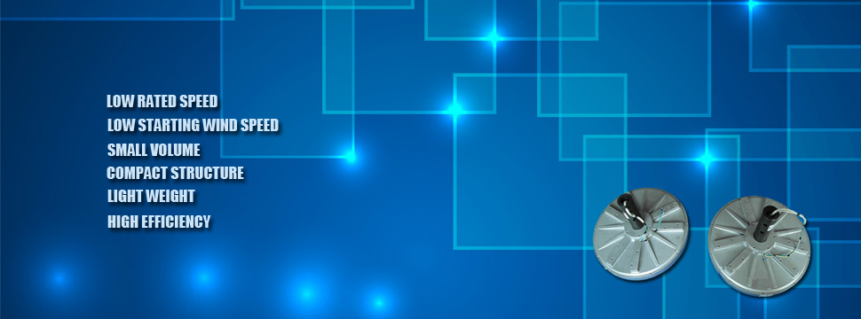
Located in the Hefei of Anhui province, city of China Science and Education, Hefei Top Grand Energy Technology Co., Ltd closes to the Oriental Pearl Tower-Shanghai, with superior geographical position and convenient transportation. In almost 6 years’ development, our Top Grand team has been building products with excellent performance employing the most advanced technologies. Our independently developed disc coreless Permanent Magnet Generator series, from 300W to 270KW, and the maximum capacity of 270KW was originated in China. They are widely used inwind power,diesel power, hydropower and other fields, which have low rated speed, low starting wind speed, small volume, less energy consumption, light weight, compact structure, high efficiency and many other features.Therefore,the productsare exported to Europe, North America, Africa, Southeast Asia and others, meanwhile have got full satisfaction and high praise of customers. Anyway, Top Grand team will do more and better works in the next days, and provide a continuous supply of good quality and professional service to customers worldwide.
The disc coreless Permanent Magnet Generator, mainly using high-performance rare earth NdFeB permanent magnet materials as the rotormaterial, coreless, anhysteresis, slotless, adopting unique coreless precision winding technology designs precision coil, using rare earthpermanent magnet materials, which is multipole, mean gap, high power density and power output. Meanwhile, it is low speed direct driving, without torque fluctuations, compact structure and high volume power ratio. No iron loss, low calorific value, small temperature rise, simple structure, easy to install, the brushless structure and free maintenance, the disc coreless Permanent Magnet Generator is the upgrading and updating of speed-regulating motor, which keeps all the advantages of the traditional DC motors, and overcomes the defects of the carbon brush and slip ring structure complexity and high failure rate.
